Cat 6 Poe Camera Wiring Diagram / Hardware Installation Gige Cameras Basler - Pin 1, 2, 3, 6 are for data transfer while pin 4, 5, 7, 8 are for poe power supply.
Cat 6 Poe Camera Wiring Diagram / Hardware Installation Gige Cameras Basler - Pin 1, 2, 3, 6 are for data transfer while pin 4, 5, 7, 8 are for poe power supply.. I had two damaged cameras but the solutions here did not work for my camera models. The nvr uses another pair to talk to the camera wire #3 and #6. In most cases you run your video and power to and from the camera on the same cat5 or cat6 wire, assuming you are using a poe (power over ethernet) power source such as a poe injector or poe switch. This is what worked for me. A wiring diagram is commonly made use of to troubleshoot problems and to make certain that all the connections have been made which everything exists.
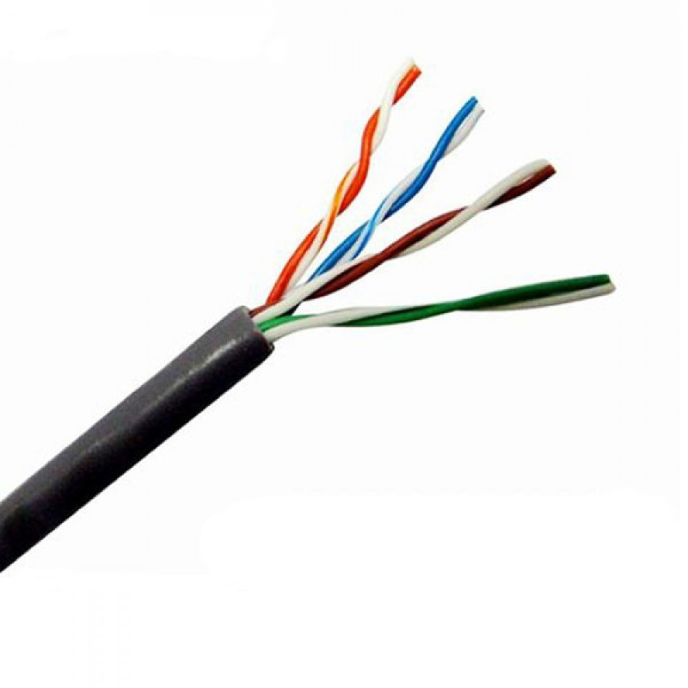
Strip wire had 8 colour inside purple,brown,orange,green,brown,blue. Each part should be placed and connected with different parts in specific way. 8 pin rj45 8p8c male connector at the cable. 8 pin rj45 8p8c male connector at the cable. Cat 5/6 ethernet cables — this type of security camera wires transmits the video/image data and power via a single cable.
Dahua Ip Camera Color Code Pinout For The Ethernet Ip Megapixel Cameras And Software Solutions Cctvforum Com from s3.us-east-2.amazonaws.com Cat 6 poe camera wiring diagram / dahua ip camera color code pinout for the ethernet ip megapixel cameras and software solutions cctvforum com. Poe camera wires to cat 5/6 connector (t568b) for these camera models. Click on the image to enlarge, and then save it to your computer by right clicking on the image. Melvin site admin posts:2238 joined:wed oct 14, 2015 2:20 pm. Here is my understanding of ip cameras and cat5: You may follow the wire order below to arrange the wires of your rj45 connector. Some other cameras may vary in their pin layout. According to earlier, the lines in a cat5 poe wiring diagram represents wires.
Each part should be placed and connected with different parts in specific way.
Hikvision ip camera rj45 pin out wiring diagram cornick dahua pinout guide comparing analog vs surveillance how power over ethernet works kintronics network installation switch faqs lorex cctv and options repair the cable on a simplified poe cat 5 crossover what are security cameras reolink rtate watt ejectie to nvr injectors page 1 line is wire learn. Orange & white pin 2: As external power doesn't needed in poe ip cameras, therefore connect only the cameras through poe via cat5 / cat 6 cables. You can use passive poe splitter and poe injector and the wire length can be 130 feet (40 meter). Each component ought to be placed and connected with different parts in particular way. Below is a description of the basic functionality of each wire associated with the ethernet port pins these cameras: Otherwise, the arrangement won't function as it ought to be. Cat 6 poe camera wiring diagram / dahua ip camera color code pinout for the ethernet ip megapixel cameras and software solutions cctvforum com. The nvr uses another pair to talk to the camera wire #3 and #6. I need to install new sockets but don't know the wiring diagram. Cat 6 poe camera wiring diagram : When i cut of the female sockets i discovered that there were only six cat5e wires instead of the four twisted pairs. To properly read a wiring diagram, one offers to learn how typically the components.
Please refer to the information below for more details Cat 5/6 ethernet cables — this type of security camera wires transmits the video/image data and power via a single cable. When i cut of the female sockets i discovered that there were only six cat5e wires instead of the four twisted pairs. As external power doesn't needed in poe ip cameras, therefore connect only the cameras through poe via cat5 / cat 6 cables. Cat 5/cat 6 poe cameras are first plugged into a poe switch/poe injector or network video recorder (nvr) with poe ports and a network router, and then.
Security Camera Cable Types Understanding Ip And Analog Cctv Cables from www.nellyssecurity.com Ip needs 2 pairs of wire to communicate with the nvr. As external power doesn't needed in poe ip cameras, therefore connect only the cameras through poe via cat5 / cat 6 cables. Security camera wire types usually include 3 main kinds: When i cut of the female sockets i discovered that there were only six cat5e wires instead of the four twisted pairs. Blue & white pin 6: You can use passive poe splitter and poe injector and the wire length can be 130 feet (40 meter). Below is a description of the basic functionality of each wire associated with the ethernet port pins these cameras: It means poe ip cameras are also known as power over ethernet cameras.
The nvr uses another pair to talk to the camera wire #3 and #6.
You may follow the wire order below to arrange the wires of your rj45 connector. If you do decide to go the cat6 route there will be a few more options. Poe cat 5 wiring diagram. Cat 6 poe camera wiring diagram : Strip wire had 8 colour inside purple,brown,orange,green,brown,blue. Cat5e poe wiring diagram : 6b4c9 rj45 poe wiring diagram poe cat5 wiring diagram wiring schematic diagram. Click on the image to enlarge, and then save it to your computer by right clicking on the image. Cat 5/6 ethernet cables — this type of security camera wires transmits the video/image data and power via a single cable. According to earlier, the lines in a cat5 poe wiring diagram represents wires. Below is a description of the basic functionality of each wire associated with the ethernet port pins these cameras: Ip needs 2 pairs of wire to communicate with the nvr. When i cut of the female sockets i discovered that there were only six cat5e wires instead of the four twisted pairs.
Below is a description of the basic functionality of each wire associated with the ethernet port pins these cameras: Each part should be placed and connected with different parts in specific way. Otherwise, the arrangement will not function as it should be. Below is a description of the basic functionality of each wire associated with the ethernet port pins these cameras: This makes the procedure for building circuit simpler.
Poe Wiring Diagram Diagrams Schematics At Diagram Wire Cat6 Cable from i.pinimg.com Brown & white pin 8: Pin 1, 2, 3, 6 are for data transfer while pin 4, 5, 7, 8 are for poe power supply. You may follow the wire order below to arrange the wires of your rj45 connector. Melvin site admin posts:2238 joined:wed oct 14, 2015 2:20 pm. To properly read a wiring diagram, one offers to learn how typically the components in the program cat6 poe wiring diagram source: I have two lorex ip cameras (model # mcnb3143) with damaged cat5e sockets. The six wires on the camera are orange, yellow, green, purple, gray, blue, and brown. 8 pin rj45 8p8c male connector at the cable.
When i cut of the female sockets i discovered that there were only six cat5e wires instead of the four twisted pairs.
In most cases you run your video and power to and from the camera on the same cat5 or cat6 wire, assuming you are using a poe (power over ethernet) power source such as a poe injector or poe switch. You can use passive poe splitter and poe injector and the wire length can be 130 feet (40 meter). Post by melvin » mon oct 23, 2017 9:17 am. A wiring diagram is commonly made use of to troubleshoot problems and to make certain that all the connections have been made which everything exists. I plan to use 2 cameras on the cat6 cable without any adapters or switch. 6b4c9 rj45 poe wiring diagram poe cat5 wiring diagram wiring schematic diagram. The cat 5/6 cables can carry the video signal up to 1,500 feet. Poe integrates data and power on the same wires it keeps the rj45 pinout wiring diagrams for cat5e or cat6 cable ethernet wiring rj45 cat6 cable from as you can see in the following diagram its necessary only to use a utp cable from the ip camera to the. Home » unlabelled » cat 6 poe camera wiring diagram / read cabling diagrams from unfavorable to positive in addition to redraw the circuit being a straight. Security camera wire types usually include 3 main kinds: It means poe ip cameras are also known as power over ethernet cameras. Blue & white pin 6: Some other cameras may vary in their pin layout.